PowerEdge: How To Export SupportAssist with a Controller Log Using the Lifecycle Controller
Résumé: This article provides information about exporting the Tech Support Report (TSR), SupportAssist (SA) Collection, and the RAID controller log using the Lifecycle Controller. This article is valid for Dell PowerEdge servers using iDRAC7 and 8 and 9. ...
Cet article concerne
Cet article ne concerne pas
Instructions
For log creation using the integrated Dell Remote Access Controller (iDRAC), see Dell article, Export Dell SupportAssist Collection and RAID Controller Log using iDRAC7 + 8.

Note:
- iDRAC7 firmware must be at least version 2.10.10.10 to offer the option of creating a RAID controller log.
- Since iDRAC firmware version 2.30.30.30, the former Tech Support Report is called SupportAssist Collection
- USB driver must be FAT-32 format for the Lifecycle Controller to recognize it.
Steps:
- Boot the server and press F10 to enter the Lifecycle Controller.
- Select Hardware Diagnostics from the list on the left and select Export SupportAssist collection as shown below.
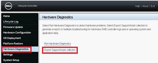
Figure 1: Hardware Diagnostics
-
This takes you to the Terms and Conditions screen, check the box to Agree then click Next at the bottom of the screen.
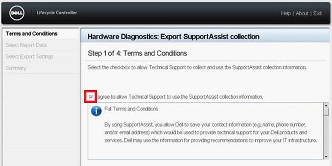
Figure 2: Terms and Conditions
-
Be sure to select Hardware and RAID Controller Logs (or operating system and Application Data if needed), then click Next at the bottom of the screen.
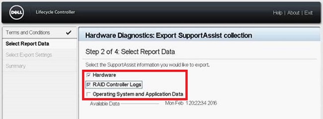
Figure 3: Log Selection
-
Insert a USB drive (FAT-32 format) or select the appropriate Network Share and enter the location data. Click Next at the bottom of the screen and Finish to complete the process.
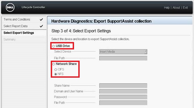
Figure 4: Log Export
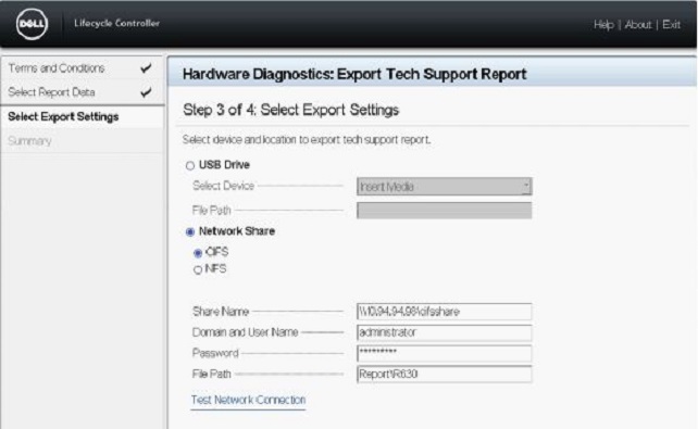
Figure 5: Sample Network Share configuration using CFS
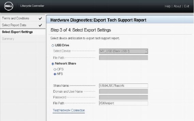
Figure 6: Sample Network Share configuration using NFS
Note: Click Test Network Connection to verify if the Lifecycle Controller UI can connect to the IP address that is provided. By default, it pings the Gateway IP, DNS server IP, host IP, and Proxy IP. Dependent on your configuration, the Network Share name may be the corresponding IP address.
Error Messages
- Error message when there is a failure in retrieving the selected report data
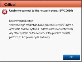
- Error message when Lifecycle Controller is unable to connect to the network share
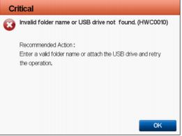
- Error message when the export fails because you have provided an invalid folder name or the USB drive is not found
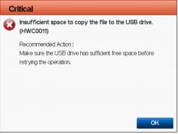
- Error message when the export fails because there is not enough space to copy to the USB drive
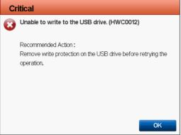
- Error message when the export fails because the USB drive is read-only
Informations supplémentaires
This video how to export a SupportAssist collection and a RAID controller log from the LCC and to save it onto a USB: