Article Number: 000188491
PowerStore: How PowerStore physical capacity is calculated
Summary: The following Article provides a high-level description of how Physical Capacity is calculated in PowerStore Appliances.
Article Content
Instructions
Before you begin
It is highly advised to first get familiar with the below concepts described in Dell EMC PowerStore: Clustering and High Availability document, section 3.2:
- Dynamic Resiliency Engine (DRE)
DRE, in short, is a representation of the aggregate space that is provided by the underlying drives, including spare and parity. - Resiliency Sets (RRS)
This represents a group of drives acting as a single failure domain. An RRS can sustain either a single drive failure (DRE SP - Single Parity or Single Tolerance), or a dual drive failure (DRE DP - Double Parity or Double Tolerance).- With DRE SP, an RRS can be as small as six drives, and as big as 25 drives.
- Starting with PowerStoreOS 2.0, DRE DP is supported. With DRE DP, an RRS can be as small as seven drives, and as big as 50 drives.
- Each RRS contains spare capacity (A single drive worth of space) and parity information.
Appliance DRE capacity
DRE capacity represents the capacity that is based on DRE Protection and DRE geometry and the number of drives.
- DRE Protection defines which DRE policy or Tolerance Level is used (DRE SP, DRE DP). The Tolerance Level for each appliance is shown in the PowerStore Manager UI under Hardware > APPLIANCES (The Tolerance Level column may have to be manually added to the UI view).
- DRE Geometry defines how drives are internally grouped (4+1, 8+1, 4+2, 8+2, 16+2). This information is not shown in the UI.
- Spare space is also included when internally calculating the DRE capacity.
Appliance Internal reserved capacity
Internal-reserved capacity represents the capacity that is required for the proper functionality of the system after initialization.
- This information is not exposed in the UI.
- Depends on the model and amount of space that is provided by DRE
- The bigger the model, the bigger "internal reserved space" is.
- The bigger the space provided by DRE, the bigger "internal reserved space" is.
- Examples of users of Internal Reserved Capacity: Internal Space for Appliance functionality (Binaries, Databases, scripts and more), reserved space for recovery mechanisms and more
Appliance Total Physical Capacity
The Appliance Total Physical Capacity is a representation of the capacity that the user can provision and use for various services such as Volumes, Snapshots, Clones, and more.
Appliance Total Physical Capacity = Appliance DRE capacity - Appliance Internal reserved capacity
Appliance Total Physical Capacity is shown in the UI: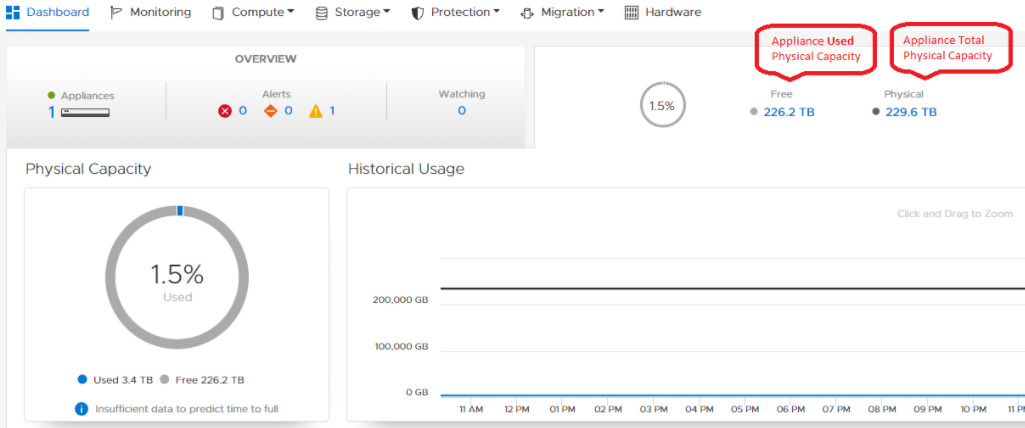
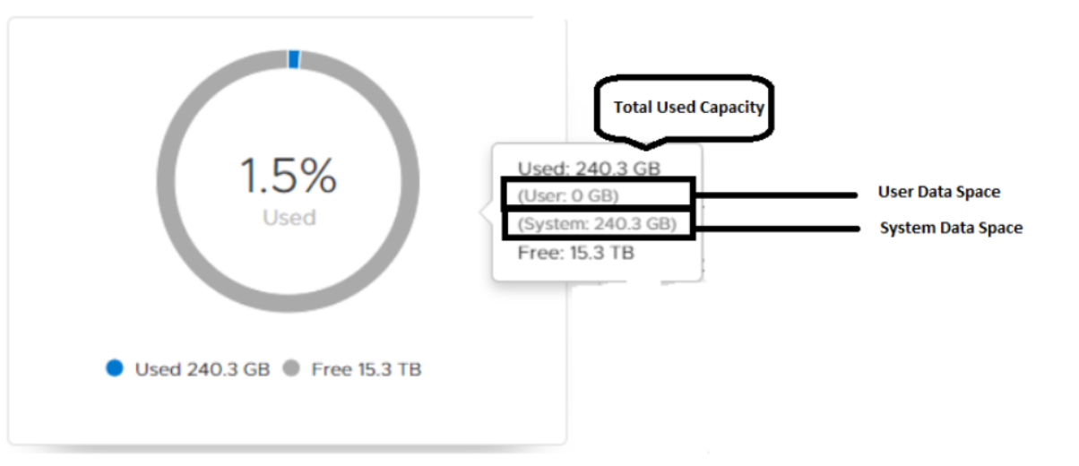
Appliance Used Physical Capacity
The Used Physical Capacity includes two types of data:
- User Data: User Data represents the data that is written to the array and used by services such as snapshots, replication, and clones. It represents the raw data (following data savings, including deduplication and compression).
Upon initialization, no User capacity is preallocated, it is allocated capacity as required. - System Data: The PowerStore array includes various metadata structures responsible for the various services such as deduplication, compression, proper functionality of the system and more
You can see a breakdown of the space that is allocated for System Data, and for User Data, by hovering above Physical Capacity.
Upon initialization, System Data preallocates some space and it grows as required.
The following can impact System Data: High compression, High Deduplication, Snapshots, and more.
NOTE: The UI displays by default the Base 2 value, while most of us are used to looking at Base 10 values of capacity.
1 kilobyte (kB) is equal to 1,000 (103) bytes.
1 kibibyte (KiB) is equal to 1,024 (210) bytes.
As seen, there is a difference between using Base 2 and Base 10, which may sometimes lead to confusion.
PowerStore reports in the UI with both Base 2 values (TiB) and Base 10 (TB), and presents the Base 2 values.
In the example below, we can see the system reports having 26.9 TiB (base 2), which equals 29.5 TB (Base 10).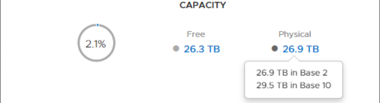
NOTE:
PowerStore Manager displays by default the Base 2 value, while most of us are used to looking at Base 10 values of capacity.
PowerStore Manager displays by default the Base 2 value, while most of us are used to looking at Base 10 values of capacity.
1 kilobyte (kB) is equal to 1,000 (103) bytes.
1 kibibyte (KiB) is equal to 1,024 (210) bytes.
As seen, there is a difference between using Base 2 and Base 10, which may sometimes lead to confusion.
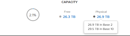
PowerStore reports in the UI with both Base 2 values (TiB) and Base 10 (TB), and by default presents the Base 2 values.
In the example below, we can see the system reports having 26.9 TiB (base 2), which equals 29.5 TB (Base 10).
Article Properties
Affected Product
PowerStore
Last Published Date
15 Jul 2024
Version
6
Article Type
How To