A Reference Guide to XPS Desktop Diagnostic Indicators
Summary: This article is a reference guide to the Diagnostics LEDs and Beeps on an XPS Tower and All in One (AIO) Desktops.
Instructions
Dell XPS desktops have a long history of integrated diagnostic indicators. These can be audible beeps, power buttons that display different states and colors, specific diagnostics LEDs or a combination of them all. In order to indicate at which point during the Power On Self-Test (POST) a device is having issues.
The following article is a reference guide to the codes available on each model and what those codes mean. They change through the various models and years. These indicators are merely a starting point. A place to narrow down any troubleshooting carried out to identify the cause of the current issue. Use this to narrow down the proper troubleshooting guide required. Alternatively, contact technical support for further help, and they are looking for these indicators as well.
Here are some resources:
- A Reference Guide to the XPS Laptop Diagnostic Indicators
- How to Diagnose and Resolve Common Memory Issues on a Dell Desktop
- Understanding Beep Codes on a Dell Desktops
Table of Contents:
- Diagnostic LEDs for the XPS Desktop series (2020 to 2025)
- Diagnostic LEDs for the XPS Desktop series (2015 to 2020)
- Diagnostic LEDs for the XPS Desktop series (2008 to 2015)
- Diagnostic LEDs for the XPS Desktop Series (2007 to 2008)
- XPS Desktop Audible Beep Codes
- Glossary of Acronyms
- Diagnostic Indicator Guides
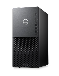
Diagnostic LEDs for the XPS Desktop series (2020 to 2025)
With the latest series, the diagnostics indicator Beeps have been removed from Tower desktops, but remains in AIO desktops. Instead the Power Button state now gives a blink and color shift pattern to indicate where it is having a problem.
| Power Button LED | Status | Power State | Description |
|---|---|---|---|
 |
Off | S4 or S5 | The power is Off. LED is blank. |
 |
Solid Amber | - | Boot Failure - This is a system fault, error condition, and includes the power supply. Only the +5VSB rail on the power supply is working correctly. |
 |
Blinking Amber | - | Boot Failure - The desktop is receiving electrical power, and the power that is supplied by the power supply is normal. A device might be malfunctioning or incorrectly installed. Refer to the table below for Amber Blinking Pattern diagnostic suggestions and possible failures. |
 |
Solid White | S0 | System is in S0 state. This is the normal power states of a functioning machine. The BIOS turns the LED to this state to indicate it has started fetching opcodes. |
 |
Blinking White | S1 or S3 | Device is in a low-power state, either S1 or S3. This does not indicate a fault condition. |
| Power LED | Problem Description | Suggested Resolution |
|---|---|---|
| 1,2 | Trusted Platform Module (TPM) Detection Failure | Contact Technical Support. |
| 2,1 | Processor Failure | Run the Intel CPU diagnostic tool |
| 2,2 | Motherboard: BIOS ROM Failure | Flash BIOS and contact Technical Support if the issue persists. |
| 2,3 | No Memory or RAM Detected | Troubleshoot the Memory and Memory Slots. |
| 2,4 | Memory or RAM Failure | Troubleshoot the Memory and Memory Slots. |
| 2,5 | Memory configuration or incompatible error | Troubleshoot the Memory and Memory Slots. |
| 2,6 | Motherboard or Chipset error | Flash BIOS and contact Technical Support if the issue persists. |
| 3,1 | Bad Coin Cell Battery | Replace the CMOS Battery and Contact Technical Support if the issue persists. |
| 3,2 | Peripheral Component Interconnect (PCI) Device or Video Subsystem failure. | Troubleshoot a No POST issue. |
| 3,3 | BIOS Recovery 1: BIOS Recovery image not found | Flash BIOS and contact Technical Support if the issue persists. |
| 3,4 | BIOS Recovery 2: BIOS Recovery image found but invalid. | Flash BIOS and contact Technical Support if the issue persists. |
| 3,5 | Power Rail Failure: Embedded Controller (EC) ran into power sequencing failure. | Contact Technical Support. |
| 3,6 | System BIOS flash incomplete. | Flash the BIOS again and contact Technical Support if the issue persists. |
| 3,7 | Management Engine (ME) error | Timeout waiting on the ME to reply to the Host-Embedded Controller Interface (HECI) message. Contact Technical Support. |
| 4,2 | Power Rail Failure | Flash BIOS and contact Technical Support if the issue persists. |
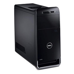
Diagnostic LEDs for the XPS Desktop series (2015 to 2020)
With this series, the diagnostics indicator Beeps were removed from Tower desktops, but remained in the AIO desktops. Instead the Power Button state gives a blink and color shift pattern to indicate where it is having a problem.
| Power Button LED | Status | Power State | Description |
|---|---|---|---|
 |
Off | S4 or S5 | The power is Off. LED is blank. |
 |
Blinking Amber | - | The state of the LED at power-up. Refer to the table below for Blinking Amber pattern diagnostic suggestions and possible failures. |
 |
Solid Amber | - | The second state of the LED at power-up indicates that the POWER_GOOD signal is active. That it is probable that the power supply is fine. |
 |
Blinking White | S1 or S3 | The Device is in a low-power state, either S1 or S3. This does not indicate a fault condition. |
 |
Solid White | S0 | The device is in S0 state. This is the normal power states of a functioning machine. The BIOS turns the LED to this state to indicate it has started fetching op-codes. |
| Power LED | Problem Description | Suggested Resolution |
|---|---|---|
| 2,1 | Motherboard Failure | Contact Technical Support. |
| 2,2 | Motherboard: Power Supply | Contact Technical Support. |
| 2,3 | Motherboard: Memory or CPU | Troubleshoot the Memory and Memory Slots. |
| 2,4 | Bad Coin Cell Battery | Replace the CMOS Battery and Contact Technical Support if the issue persists. |
| 2,5 | BIOS Checksum Failure | Flash BIOS and contact Technical Support if the issue persists. |
| 2,6 | Bad CPU | Contact Technical Support. |
| 2,7 | Memory Failures | Troubleshoot the Memory and Memory Slots. |
| 3,1 | PCI Device or Video Subsystem failure | Troubleshoot a No POST issue. |
| 3,2 | Video Subsystem failure | Troubleshoot a No POST issue. |
| 3,3 | No Memory detected | Troubleshoot the Memory and Memory Slots. |
| 3,4 | Storage Subsystem failure | Troubleshoot a No POST issue. |
| 3,5 | Memory configuration or incompatible error | Troubleshoot the Memory and Memory Slots. |
| 3,6 | System board failure | Troubleshoot a No POST issue. |
| 3,7 | Possible Memory failure | Troubleshoot the Memory and Memory Slots. |
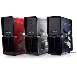
Diagnostic LEDs for the XPS Desktop series (2008 to 2015)
This series uses power button LED states. The power button is located on the front of the chassis. Identify these models by their flat black front face and side panels and lids.
| LED Status | System State | Suggested Next Step | |
|---|---|---|---|
| Off |  |
The device is either turned off or is not receiving power. | Troubleshoot a No Power issue. |
| Blinking Amber |  |
The device is receiving power, a device might be faulty or incorrectly installed. | Troubleshoot a No POST issue. |
| Solid Amber |  |
The device is in standby. | Press a key on the keyboard, move the mouse, or press the power button to resume normal operation. If the problem persists, listen for a beep code. |
| Solid White |  |
The device is on and working ok. | If the device is not responding, troubleshoot a: No Boot or No Video issue |
XPS 430s to 360s, 730s, and 8300s to A2420's
| Diagnostic Beep Codes | |||
|---|---|---|---|
| LED Status | Beep Code | Cause | Suggested Resolution |
 |
1 | BIOS ROM Checksum in progress or failure | Contact Technical Support. |
 |
2 | No memory modules detected | Troubleshoot the Memory and Memory Slots. |
 |
3 | Chipset Error
Time-of-day clock test failure Gate A20 Failure Super I/O chip Failure Keyboard controller test failure |
Contact Technical Support. |
 |
4 | RAM read/write error | Troubleshoot the Memory and Memory Slots. |
 |
5 | Real-Time Clock Failure | Replace the CMOS Battery, Contact Technical Support if the problem persists. |
 |
6 | Video BIOS test Failure | Run the Dell Diagnostics. |
 |
7 | CPU Cache Test Failure | Contact Technical Support. |
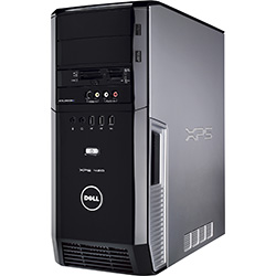
Diagnostic LEDs for the XPS Desktop series (2007 to 2008)
This series used power button LED states and a diagnostics LED pack on Towers and AIO desktops.
| LED Status | System State | Suggested Next Step | |
|---|---|---|---|
| Off |  |
The device is either turned off or is not receiving power. | Troubleshoot a No Power issue. |
| Blinking Amber |  |
The device is receiving power, a device might be faulty or incorrectly installed. | Troubleshoot a No POST issue. |
| Solid Amber |  |
The device is in a fault condition including the power supply. | Troubleshoot a No POST issue. |
| Blinking Blue |  |
The device is in Standby. | Press a key on the keyboard, move the mouse, or press the power button to resume normal operation. If the problem persists, listen for a beep code. |
| Solid Blue |  |
The device is on and working ok. | If the device is not responding, troubleshoot a: No Boot or No Video issue |
XPS 420s, 600s, 700s to 720s and A2010's to A2420's
| Diagnostic LED Status | Light Pattern | Problem Description | Suggested Next Step |
|---|---|---|---|
 |
    |
The device is in a normal.
off state, or is possibly a pre-BIOS failure has occurred. If the device Boots the diagnostic LEDs turn off. |
Reseat all power and data cables. |
| N/A |     |
System is in recovery mode. | Contact Technical Support. |
 |
    |
A possible Processor Failure has.
occurred |
Contact Technical Support. |
 |
    |
Memory modules are detected, but a
memory failure has occurred |
Troubleshoot the:
Memory and Memory Slots |
 |
    |
A possible graphics failure has occurred. | Troubleshoot a: No POST issue |
 |
    |
A possible Floppy Disk Drive (FDD) or hard drive Failure has.
occurred |
Reseat all power and data cables. |
 |
    |
A possible USB Failure has occurred. | Reinstall all USB devices and check.
all USB cable connections |
 |
    |
No memory modules are detected. | Troubleshoot the:
Memory and Memory Slots |
 |
    |
Memory modules are detected, but
a memory configuration or compatibility error has occurred |
Troubleshoot the:
Memory and Memory Slots |
| N/A |     |
A possible expansion card failure
has occurred |
Troubleshoot a: No POST issue |
| N/A |     |
Other Pre-Video activity | Troubleshoot a: No POST issue |
 |
    |
System resource configuration in Process | Troubleshoot a: No POST issue |
 |
    |
Another failure has occurred Post.
Video activity |
Troubleshoot a: No POST issue |
| N/A |     |
Handed off to Boot | The POST sequence has ended
and the Boot startup has begun |
XPS Desktop audible Beep codes
In addition to the various types of diagnostics LEDs, there are several audible beep codes across some of the models of these devices.
These codes are recognized across manufacturers and have remained the same for some time.
The keys to these codes are displayed in the table below.
| Diagnostic Beep Codes | ||
|---|---|---|
| Code | Cause | Suggested Resolution |
| 1 | BIOS ROM Checksum in progress or failure | Contact Technical Support. |
| 2 | No memory modules detected | Troubleshoot the Memory and Memory Slots. |
| 3 | Chipset Error
Time-of-day clock test failure Gate A20 Failure Super I/O chip Failure Keyboard controller test failure |
Contact Technical Support. |
| 4 | RAM read/write error | Troubleshoot the Memory and Memory Slots. |
| 5 | Real-Time Clock Failure | Replace the CMOS Battery, Contact Technical Support if the problem persists. |
| 6 | Video BIOS test Failure | Run the Dell Diagnostics. |
| 7 | CPU Cache Test Failure | Contact Technical Support. |
Glossary of Acronyms:
Refer to the table for definitions of the acronyms within this article.
| Acronym | Definition |
|---|---|
| BIOS | Basic Input/Output System |
| CFG | Resource Configuration |
| CPU | Central Processing Unit |
| DIMM | Dual inline memory module |
| DMA | Direct Memory Access |
| EC | Embedded Controller |
| HECI | Host Embedded Controller Interface |
| LCD | Liquid Crystal Display |
| LED | Light Emitting Diode |
| MBF | Motherboard Failure |
| MBIST | Memory Built-in Self-Test |
| ME | Management Engine |
| MEM | Memory |
| NVRAM | Non-Volatile Random Access Memory |
| PCI | Peripheral Component Interconnect |
| POV | Postvideo Activity |
| PRV | Prevideo Activity |
| PSU | Power Supply Unit |
| RAM | Random Access Memory |
| RCM | Recovery Mode |
| ROM | Read-Only Memory |
| RTC | Real-Time Clock |
| S0 | System Power State S0 - This is the Working State, where your Windows device is awake. |
| S1 | System Power State S1 - In this sleep state, the CPU is stopped, and your device is in standby mode. |
| S2 | System Power State S2 - This state is similar to S1 except that the CPU and system cache are lost because the processor loses power. |
| S3 | System Power State S3 - In this state, data is saved to RAM, hard drives, and other hardware are shut down. |
| S4 | System Power State S4 - In this state, RAM and other data are saved to the hard disk. |
| S5 | System Power State S5 - The System is off. |
| SBIOS | Small Board Interface Operating System |
| SPI | Serial Peripheral Interface |
| STD | Boot Hand Off |
| STO | Storage Device |
| TPM | Trusted Platform Module |
| USB | Universal Serial Bus |
| VID | Video |
If it is a recognizable code, follow the instructions. If contacting the local support, ensure that the code information is to hand. The technician needs this information to help further.
If it is an unrecognizable code, one that is not listed above - then get in touch with the local support straight away.
If further assistance is required: contact Dell Technical Support